MOLD DESIGN FOR VENTING AND COOLING
Using Negative Pressure
How to design better molds by venting into the water line and improve cycles by transferring coolant from one half of the mold to the other – plus other innovative techniques that also improve processing, part quality, and cycle time.
VENTING
INCREASED NEED FOR VENTING
Every molder is aware of the basic need to vent molds of the air that is trapped in them; else suffer as that air is compressed, overheats and causes burns on the plastic. In some cases the combination of high temperature and volatile gases can damage the mold by etching it away. Inadequate venting also impedes complete filling of the part, as the highly compressed air competes with the injection pressure of the machine. The molder is also likely to attempt to fill the mold slower to avoid the burn; this, of course, also makes it more difficult to fill the mold completely.
In recent years, however, the problem of venting has become even more difficult. The culprits are the newer resins that have been developed for engineering applications. The styrenes, polypropylenes and polyethylenes that were the workhouse resins of a few years ago have been supplemented with the addition of polycarbonate, acetyl, PVC, ABS and many other new resins and co-polymers. The trouble is that many of these newer formulations are "gasier" then their older counterparts. They give off their own gases, as they are processed, that add to the air already in the cavity, compounding the venting problem. In addition, we are seeing increasing use of fillers, stabilizers, pigments and additives of all kinds, intended to improve UV resistance, color fading, microbial resistance, and so on—all of which can add to the gassing-venting dilemma facing today’s injection molder.
VENTING INTO THE WATER LINETM
THROUGH FILTER SCREEN OR POROUS METAL
One way to attack the need for improved venting is to greatly enlarge the venting area. This has been attempted in the past by using porous metal which allows gases to pass through, but not plastic—at least until it overheats, as it is prone to do because of its poor heat transfer ability. But now we have a method to directly cool that porous metal that was not possible until the advent of negative-pressure coolant technology. With it, the porous metal slug, backed by a properly designed steel reinforcement, is directly cooled by the mold coolant without leaking.
A typical application would be a part shaped like a lipstick tube. With Waterline VentingTM, such a part can be gated at its base, allowing the top to retain a perfect, cosmetic finish. At the tip of the core, forming the inside of the part, is a porous metal or woven metal screen, backed by a steel insert with several 0.020" holes drilled in it, connected with the pick-up grooves. Behind this is a conventional bubbler assembly, bringing coolant right up to the vent screen, keeping it cool at all times. The screen never overheats and gets plugged with plastic.
In addition to the new mold configuration that is possible, allowing the part to be gated inconspicuously at the base, this design provides tremendously improved mold venting.
THROUGH EJECTOR PINS
Another way to achieve improved venting is through ejector pins – directly in the waterline. Several advantages accrue to this method. Since the pins run directly through the coolant, they won’t overheat and become plugged with oil-like deposits that can result from degraded plastic—which in turn reduces their venting ability and simply adds to the problem.
Another important advantage is that the toolmaker is not constrained by the placement of pins, which can be located for maximum venting and ejection effectiveness, and water channels, which can be placed for maximum cooling. Finally, toolmakers, already familiar with the conventional technique of venting through ejector pins to the atmosphere, may feel more comfortable with this method before they tackle venting through porous metal.
THE DESIGN OF A REGULAR VENT
Please take the time to reason out and understand this statement:
When the mold closes with clamp pressure, the parting line should not touch anywhere!!
This is a fact and when designing the venting system, do just that, design it. Don't leave it to do after sample parts are made. You will:
1. Open up the molding machine setting to get good parts.
2. Have less maintenance on the tool over it's life.
3. Be able to increase the quality of the parts you produce with the
same or less cost.
Does doing the above cost more?
1. On round flat parting line - nothing
2. On four sided flat parts - very little
3. On complex parting lines it can cost too much to do.
So do it wherever you can, but never do venting without considering how much surface area of steel (etc.) you are taking away from the clamping force.
For more details of vent design contact us.
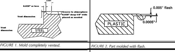
* For more information you can refer to the article "Flash: It's ruining your molds" in the May issue of Society of Plastic Engineers magazine. www.4spe.org
COOLING
WATER TRANSFERTM
Water TransferTM allows you to transfer coolant from one half of the mold to the other. Why would you want to do that? The primary application is to cool long, thin cores, such as pen barrels (or thinner). The problem with traditional bubblers is that they must be so small that they restrict the water flow, can become easily plugged, and are not perfectly straight thus provide uneven cooling at the tip, just where it is usually most needed. The mechanics of Water TransferTM are straightforward. When the mold is closed, the coolant flows through the core into the other half of the mold, and back to the negative-pressure pump, which prevents leaks. Just before the mold opens, the supply valve is closed and a vent valve is opened in order to evacuate the line and the tool of water at the transfer point.
The amount of cooling is increased manyfold. There are no more problems with plugged or off-center bubblers. Cooling at the very tip is just as effective as at any other point. More over, a nice side benefit is that the tip of the core can easily be used to vent molding gases into the water lines.
OTHER COOLING TECHNIQUES
PUT COOLANT ONLY WHERE IT IS NEEDED
With negative pressure, leaks are no longer a concern of the mold designer. Coolant channels can be put exactly where they are needed—right next to the plastic. We have already described how coolant can be passed right over ejector pins, keeping them cool and venting to the water line. It also permits the coolant to pass close to the plastic. This eliminates the problem of needlessly cooling the mold frame, and creating temperature differentials, poor part cooling, and mold sweating.
An example is a plastic clothes hanger. The coolant can be placed to closely follow the contour of the part, rather than cool the entire mold and have the mold surface sweat and limit your cycles and/or reject parts.
PUT COOLANT DIRECTLY BEHIND MOLD BLOCK
Another technique that can be used is a grill-like network placed directly behind the mold block so that the coolant contacts it directly. This is especially beneficial for broad, flat parts. This sort of mold design is made easy by the proper use of negative pressure.
CONTACT COOLINGTM
Contact CoolingTM is just what it says: the coolant actually touches the molded plastic part directly. Of course, not all parts can benefit from this, as it may not leave a cosmetic finish. However, it is viable for a great many parts. As with so many other "radical" techniques, it is made quite simple by the use of negative pressure. A porous plug, made of pressed or woven material, is inserted where the cooling is needed. While the mold is open, and until the cavity is filled with plastic, negative pressure is applied so that coolant flows by the plug, but not through it. After the cavity is filled, positive pressure is applied, forcing the coolant through the plug and directly onto the surface of the plastic.
Even the thickest sections can be adequately cooled in this way. Moreover, thinner sections, that can be controlled by more "conventional" cooling, can benefit from tremendous decreases in cycle time permitted by Contact CoolingTM. Contact CoolingTM works because it eliminates this paradox: sinks cause sinks. In the traditional mold, the only cooling of the plastic takes place as it touches the metal of the cavity/core. As soon as a sink begins, it is no longer touching the walls of the mold, and the still-hot center of the molded part reheats the skin, and the sink gets worse. Only Contact Cooling can break the cycle.
BUBBLER HUNT
The last method is really just a tip that works on all long bubblers, with or without negative pressure. A common problem with long cores is that they have no support other than at the base, where they are attached. At the tip of the core, they are far off-center sometimes close to or actually touching one wall of the coolant channel. This gives uneven cooling, and it is the beginning of perhaps no cooling at all, as the narrow passage is an ideal place for small solids to start plugging the return from the bubbler. As with so many other things, it simply makes itself worse; the plugging further slows the coolant flow, increasing the potential for more plugging, and so on.
Also like many other things that go wrong, prevention is a lot less painful than the cure. Simply cut three small "V" slots in the tip of the bubbler tube, and spread the three remaining "leaves" so that they are pressed against the inside of the coolant channel when the tube is inserted. Thus it will remain centered, provide even cooling, and prevent "no flow areas" where deposits settle out and often cause complete plugging.
SUMMARY
We have described many innovative ways to vent and cool injection molds. These techniques will give you faster cycles, better parts, and make it easier to mold a high-quality part. We have reviewed the following methods:
Increasing venting with Waterline VentingTM, through porous metal and through ejector pins.
Peripheral venting including ejector pin;
Water TransferTM, including venting;
Putting coolant only where it is needed, following the contours of a part;
Putting coolant directly behind the mold block, such as for broad, flat parts;
Contact CoolingTM to directly cool the molded part with coolant;
And finally, a tip on how to keep long bubbler tubes centered to prevent uneven cooling and potentially plugging up.
|